MAIN CONTRACTOR
AMCO
CLIENT
Network Rail
LOCATION
Leyland Station, Lancashire
SCOPE OF WORKS
PROJECT BRIEF
Leyland Station is located on the West Coast Mainline. Access between the outer and central platforms was via a footbridge with staircases. This restricted passengers with limited
mobility getting from one platform to the other without having to take a 500m circuitous route via the adjacent road bridge. Direct access to the central platform was not possible for these passengers.
In order to make all areas of the station accessible to everyone; the project was to provide a new modern footbridge which could be accessed via either the staircase or a 16 person lift at each of the 3 platforms, thus making all areas to the station accessible to all.
The project came under the Access-For-All (AFA) scheme, which is funded by the Department for Transport.
KEY ISSUES
- A footbridge was required to be founded upon 54no 273mm diameter Bottom Driven Steel Cased (BDSC) piles up to 8.0m depth.
- After carrying out a review of the enquiry, Foundation Engineers, Roger Bullivant Limited (RB) highlighted that, due to the dense ground conditions at this location, BDSC piles were not appropriate and would not achieve the required design depth. The depth of pile would be critical to the design due to both tensile and lateral resistance required from the piles. In addition, vibration from a driven pile could allow track movement causing possible disruption to train services.
- On receipt of these concerns, AMCO asked RB to carry out two BDSC test piles within the station’s east car park, to a depth of 8m. Both of the test piles refused at only 4m deep.
SOLUTION
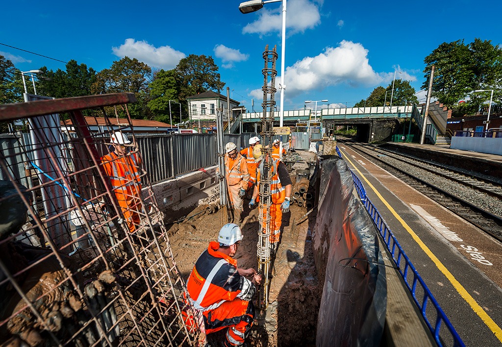
RB liaised with the main contractor AMCO and the project designers. RB offered a solution which changed the pile design from driven to bored. Also, to alleviate the project designer’s fears that the ground conditions may precipitate the pile walls collapsing during its construction, a hollow stem Sectional Flight Auger (SFA) pile was recommended and adopted as the best solution. The design was subsequently revised to SFA piles and upon completion of the final design, 69no piles were required varying from 7.0m to 12.5m deep.
-
- The main challenge was delivering all piles to an exacting program on a live platform.
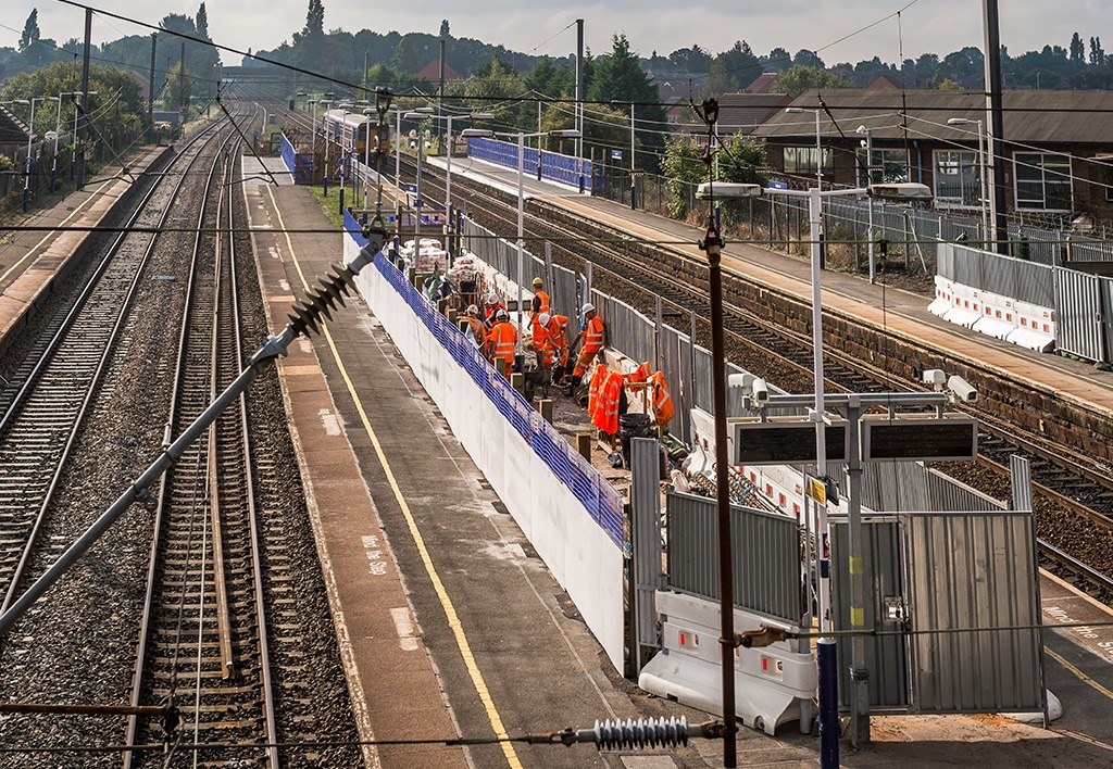
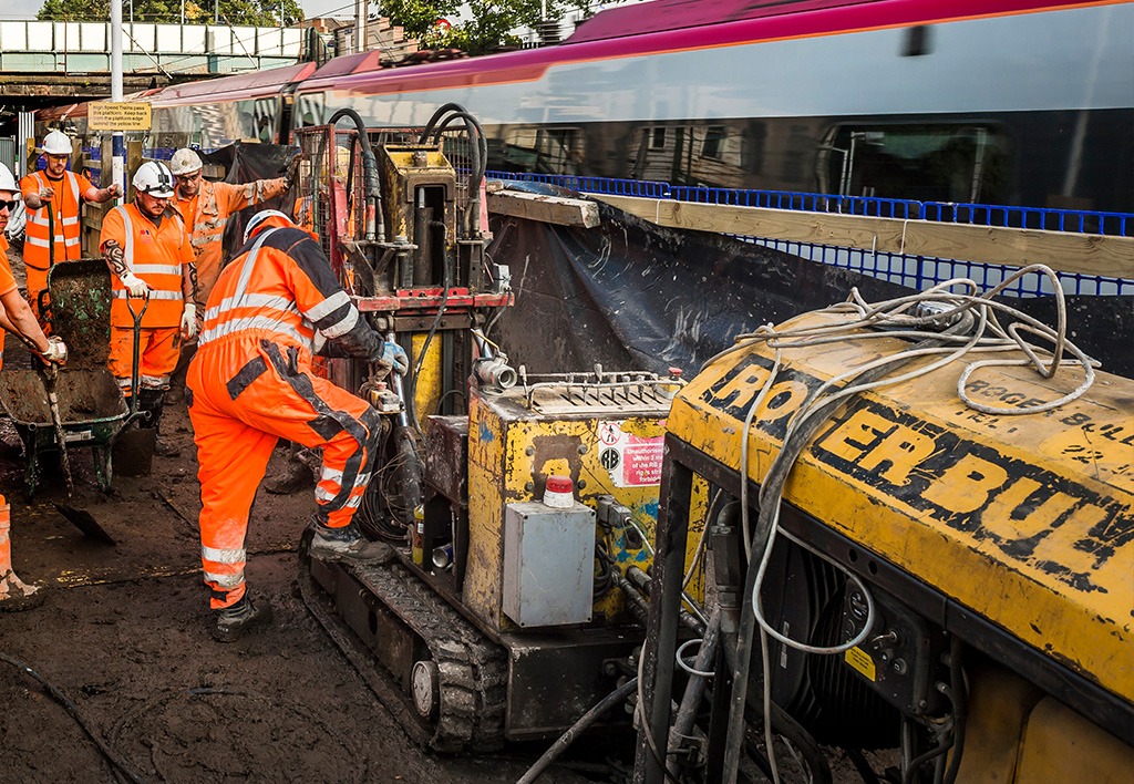
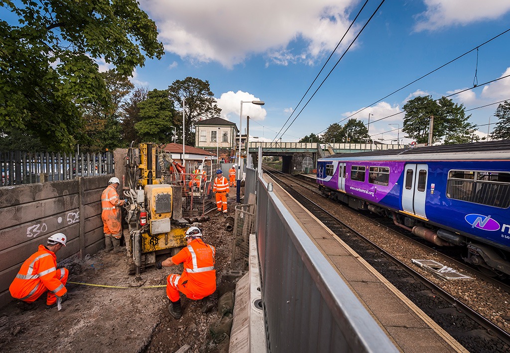
- Two rig types were utilised to install all three pile sizes; all piling works were completed behind temporary hoardings erected to protect the public during the construction sequence. The RB 905 rig was used to construct the pile types along the two outer train platforms; while the smaller RB Kitten 702 was used to construct piles within the central island platform. Both rigs were suitable for restricted access works with the Kitten rig being better suited for the tighter working restraints on the island platform (the working area of the central island platform was only 3m wide).
- The presence of overhead line electrification cables (OHLE), oncoming trains and public access to the platforms meant it was not practicable to use Ready Mix concrete.
- All the piles were grouted with site batched supplies utilising a specialist bespoke mix to satisfy the loads of the structure whilst being capable of withstanding the ground conditions present at the site.
- The whole construction process was tightly managed by RB and AMCO to ensure the safety of the workforce and public while working near open train lines.
- Due to the undisrupted train schedule through weekdays, plant movements, material deliveries and the necessary preparatory groundworks had to be completed during night operations or in weekend line possession.
- All piles were constructed as planned, during normal working hours, with no disruption to rail services.


